Reliability
Reliability stress testing on semiconductor components
Reliability Tests
Central Semiconductor performs extensive reliability stress testing on a variety of products from our product portfolio. This data is collected in addition to Central's standard qualification test data for any new or changed product.
Typical Results:
| No. | Test Item | Test Condition | Failure Rate |
|---|---|---|---|
| 1 | HTSL (Bake) | TA = 150°C, t = 1000 hours | 0/77 |
| 2 | HTRB | TA = 125°C, t = 1000 hours; Bias conditions per device datasheet | 0/77 |
| 3 | THB | TA = 85°C, RH = 85%, t = 1000 hours; Bias conditions per device datasheet | 0/77 |
| 4 | HAST | TA = 130°C, RH = 85%, t = 96 hours or TA = 110°C, RH = 85%, t = 264 hours | 0/77 |
| 5 | Temperature Cycling | (150°C for 15 min. / -65°C for 15 min.) x 1000 cycles | 0/77 |
| 6 | Thermal Shock | Liquid to Liquid (-65°C to 150°C) x 1000 cycles | 0/77 |
| 7 | Autoclave | TA = 121°C, p = 15 PSIG, t = 96 hours | 0/77 |
| 8 | Solderability | Steam age = 8 hours, T(Solder) = 245°C, t = 5 sec. | 0/77 |
| 9 | Solder Shock | T(Solder) = 260°C, t = 10 sec. | 0/77 |
FIT Rate (HTRB Life)
Data noted herein is based on standard FIT rate calculations as detailed below.
FIT Rate Calculations
| Product Type | Package Type | Failure Type (FITS) |
|---|---|---|
| Bipolar Power Transistors |
DPAK
|
4.22
|
| Transistor |
SOIC-8, SOT-26, SOT-363, SOT-883L
SOT-223
SOT-23
SOT-323, SOT-523, SOT-563, SOT-923, SOT-953
SOT-89
|
2.52
3.48
2.15
2.30
3.78
|
| Fast, Ultra, Super and HyperFastA Rectifiers |
D2PAK
DPAK
MELF
SMA, SMAFL, TLM364
SMB,SMBFL, TLM364
SOD-123F
|
5.68
4.22
2.89
3.48
3.48
2.15
|
| Switching Diodes |
SOD-123, SOT-23
SOD-323, SOD-523, SOD-923, SOT-323, SOT-523, SOT-563
SOD-80
SOT-363
|
2.15
2.30
2.89
2.52
|
| Zener Diodes |
SMA, TLM2D3D6
SOD-123, SOT-23
SOD-323, SOD-523, SOD-923, SOT-563
SOD-80, MELF
SOT-363
|
3.48
2.15
2.30
2.89
2.52
|
Reliability Formulas
The failure rate calculation based on a single life test is as follows:
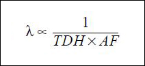.jpg "failure_rate_calculation-(1).jpg")
λ = Failure Rate
TDH = Total Device Hours
AF = Acceleration Factor
The Acceleration Factor is calculated as follows:
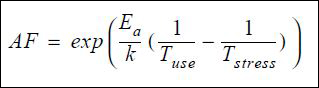.jpg "accelleration_factor-(1).jpg")
Ea = Thermal Activation Energy
k =Boltzmann's Constant (8.63 x 10⁻⁵ eV)/K
Tuse= Use Temperature (°C + 273)
Tstress = Life test stress temperature (°C + 273)
The comprehensive failure rate is calculated as follow:
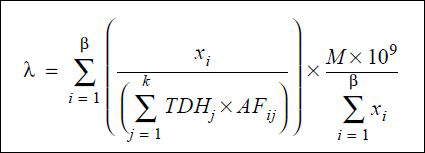.jpg "comprehensive_failure_rate-(2).jpg")
β = Number of distinct possible failure mechanisms
k = Number of life tests combined
xi = Number of failures for a given mechanism (1 = 1, 2, ... B)
TDHj = Total device hours of test time for life testj (j = 1, 2,... k)
AFij = Acceleration factor for appropriate failure mechanism (i = 1, 2,... k)
M = X² (∝ , 2r +2) / 2
(where X² = chi square factor for 2r +2 degrees of freedom, r = total number of failures, ∝ = risk associated with CL between 0 and 1
Package Reliability Summaries
Reliability Summaries for surface mount and through-hole package types can be found in the "Package Reliability" column of the tables below.